Search results
Search for "tuning fork" in Full Text gives 44 result(s) in Beilstein Journal of Nanotechnology.
Unveiling the nature of atomic defects in graphene on a metal surface
Beilstein J. Nanotechnol. 2024, 15, 416–425, doi:10.3762/bjnano.15.37

- are indeed lacking the graphene atomic lattice structure in their interior. Spatially resolved spectroscopy of the differential conductance (dI/dV, I: tunneling current, V: bias voltage) and of the tuning fork resonance frequency change (Δf) further unravel marked differences between these two kinds
- of an oscillating piezoelectric tuning fork sensor [37][38] (resonance frequency: 30.5 kHz, quality factor: 45000, amplitude: 50 pm) were mapped at constant height for topographic images. The vertical force between tip and sample was extracted from distance-dependent measurements of the resonance


A cantilever-based, ultrahigh-vacuum, low-temperature scanning probe instrument for multidimensional scanning force microscopy
Beilstein J. Nanotechnol. 2022, 13, 1120–1140, doi:10.3762/bjnano.13.95

- tuning fork force sensor became increasingly popular. In comparison to microfabricated cantilevers, the more macroscopic tuning forks, however, lack sensitivity, which limits the measurement bandwidth. Moreover, multimodal and multifrequency techniques, such as those available in cantilever-based AFM
- attractive or repulsive inter-atomic forces occur between tip apex atom and atoms at the surface. In recent years, functionalizing the tip apex with a lowly coordinated atom/molecule resulted in exceptional submolecular resolution at low temperature [8][9][10][11]. Tuning fork AFM has become increasingly
- popular for atomic resolution work performed under UHV conditions [12]. In tuning fork AFM, one of the prongs of the tuning fork is fixed to the tip holder, while the other one acts like a macroscopic cantilever. The comparatively large dimensions of the prongs facilitate the attachment of a small but


Quantitative dynamic force microscopy with inclined tip oscillation
Beilstein J. Nanotechnol. 2022, 13, 610–619, doi:10.3762/bjnano.13.53

- sensor often used in low-temperature environments (tuning fork sensor [21] with f0 = 30 kHz, k0 = 1800 N/m, and A = 0.45 nm). However, similar effects can be present when using parameters for other sensors as well. Frequency shift Δf data are calculated with the piezo axis located at xts = yts = 0 and


![[Graphic 38]](/bjnano/content/inline/2190-4286-13-53-i79.svg?max-width=637&scale=1.18182) and the axis w....
and the axis w....


Topographic signatures and manipulations of Fe atoms, CO molecules and NaCl islands on superconducting Pb(111)
Beilstein J. Nanotechnol. 2022, 13, 1–9, doi:10.3762/bjnano.13.1

- temperature in the preparation chamber. Low-temperature scanning tunneling microscope The experiments were performed using a low-temperature STM/AFM microscope (T = 4.8 K) from Omicron GmbH in UHV (p ≈ 1 × 10⁻¹⁰ mbar) operated with Nanonis RC5 electronics. The sensor is a tuning fork sensor in a qPlus design


Numerical analysis of vibration modes of a qPlus sensor with a long tip
Beilstein J. Nanotechnol. 2021, 12, 82–92, doi:10.3762/bjnano.12.7

- . The vibration modes of a qPlus sensor with a long tip are quite different from those of a cantilever with a short tip. Flexural vibration of the tungsten tip will occur. The tip can no longer be considered as a rigid body that moves with the prong of the tuning fork. Instead, it oscillates both
- the optimal diameter was found to be 0.1 mm. Keywords: finite element method; long tilted tip; noncontact atomic force microscopy; qPlus sensor; quartz tuning fork; simulations; Introduction Quartz tuning forks are widely used in the watch industry because of their low frequency offset over a wide
- temperature range [1]. In addition, quartz tuning forks have a high elastic constant, a high quality factor (Q factor), and are self-sensing due to the piezoelectric effect [1]. Therefore, a quartz tuning fork can be used as a force sensor. The central part of the “qPlus sensor” is a quartz tuning fork of


Protruding hydrogen atoms as markers for the molecular orientation of a metallocene
Beilstein J. Nanotechnol. 2020, 11, 1432–1438, doi:10.3762/bjnano.11.127

- instrument (ScientaOmicron GmbH, Taunusstein, Germany), while experiments on thin films used a ScientaOmicron LT qPlus gen.II machine, both operated with a MATRIX controller. W tips attached to tuning fork sensors in qPlus configuration [29] were used in both systems. For the measurements on thin film


![[Graphic 10]](/bjnano/content/inline/2190-4286-11-127-i10.svg?max-width=637&scale=1.18182) row of FDCA molecules in geo 2. (a–c) Constant-height frequency-shi...
row of FDCA molecules in geo 2. (a–c) Constant-height frequency-shi...
Revealing the local crystallinity of single silicon core–shell nanowires using tip-enhanced Raman spectroscopy
Beilstein J. Nanotechnol. 2020, 11, 1147–1156, doi:10.3762/bjnano.11.99

- ) along the perimeter of a SiNW. The tip–sample distance is controlled by a shear-force feedback. For this purpose, the tip is mounted on an oscillating tuning fork, which experiences a phase shift of the oscillation upon approach. This phase shift is recorded with a lock-in amplifier and fed to a
- further increase the resolution a chemically etched gold tip, attached to a tuning fork, is brought into the focus [37][38][39][40][41]. A plasmonic oscillation is generated at the tip apex by the excitation with a radially polarized laser beam along the tip axis. Here, the local field intensity is


Experimental study of an evanescent-field biosensor based on 1D photonic bandgap structures
Beilstein J. Nanotechnol. 2019, 10, 967–974, doi:10.3762/bjnano.10.97

- the photonic chip using a cleaved single-mode optical fiber and the near-field signal from the PBG structure was collected using a bent fiber tip pre-mounted on a tuning fork working in tapping mode. Figure 3 shows the SNOM signal measured for one of the PBG sensing structures having transversal
- coated, pre-mounted on a tuning fork working in tapping mode at 36.19 kHz and placed perpendicular to the sample was used to scan the photonic structures and measure the near-field signal using a FWPR-S femtowatt photoreceiver. A step size of 40 nm in the xy-plane was used when acquiring the SNOM image


Investigation of CVD graphene as-grown on Cu foil using simultaneous scanning tunneling/atomic force microscopy
Beilstein J. Nanotechnol. 2018, 9, 2953–2959, doi:10.3762/bjnano.9.274

- apex. However, the uncertainty whether there is sufficient coating at the very apex of the tip or not and whether that coating remains during the experiments casts doubt on the metallic nature of the tip. Only in a limited number of experiments where a tuning fork is used as the sensing element, W tips


Dumbbell gold nanoparticle dimer antennas with advanced optical properties
Beilstein J. Nanotechnol. 2018, 9, 2188–2197, doi:10.3762/bjnano.9.205

- advantage of AFM manipulation methods, CB[n] is ideally suited to mediate sub-nanometer gap formation. For this, a sharply pointed glass tip is glued to a piezoelectric quartz tuning fork (Figure 1C), which enables to control the tip position with respect to AuNPs deposited on a glass surface with sub
- formed of spherical AuNPs attached to a sharply pointed glass tip. Inset: Magnification to the gap region showing the aligned CB[n]s on the NP surfaces, which results in a sub-nanometer gap distance. (C) Macroscale picture of a glass tip attached to a piezoelectric quartz tuning fork acting as a force


Optical near-field mapping of plasmonic nanostructures prepared by nanosphere lithography
Beilstein J. Nanotechnol. 2018, 9, 1536–1543, doi:10.3762/bjnano.9.144

- then glued onto an Abracon Corporation, AB38T-32.768 kHz tuning fork operated in shear force configuration. Image treatment To perform the FFT analysis of the optical images we used the open source software Gwyddion [38]. Any AFM software offering these processing options could be used to achieve the


Optimizing qPlus sensor assemblies for simultaneous scanning tunneling and noncontact atomic force microscopy operation based on finite element method analysis
Beilstein J. Nanotechnol. 2017, 8, 657–666, doi:10.3762/bjnano.8.70

- lateral resolution of the setup. As a consequence, establishing a highly symmetric tunneling connection with the smallest possible stiffness should receive highest priority during the assembly of tuning fork-based sensors. Methods The results presented in the paper expand on a previously introduced
- approach for the FEM modeling of a tip-less, but otherwise complete qPlus-style sensor setup [26]. This previous model included a tuning fork of length L = 2426.3 µm, width w = 130.7 µm, and thickness τ = 234.1 µm mounted with epoxy glue on a holder made of Macor, with material choices and sensor geometry
- closely reflecting the design that we actually use in our lab. While in [26] the thickness of the epoxy layer and its overlap with the tuning fork (referred therein as parameters ‘ethick’ and ‘eover’, respectively) were varied to uncover their influence on the sensor properties, we keep them constant


Noise in NC-AFM measurements with significant tip–sample interaction
Beilstein J. Nanotechnol. 2016, 7, 1885–1904, doi:10.3762/bjnano.7.181
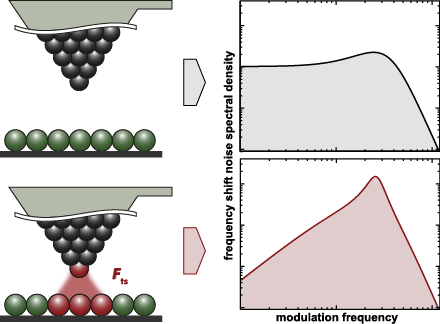
- the sample surface [2], typically a cantilever, a tuning fork, or a needle sensor [8]. The resolution of force measurements is limited by the noise in the frequency shift signal [9][10], which strongly depends on the noise floor of the detection system, the frequency response of the frequency


![[Graphic 32]](/bjnano/content/inline/2190-4286-7-181-i73.png?max-width=637&scale=1.18182) wit...
wit...

![[Graphic 34]](/bjnano/content/inline/2190-4286-7-181-i75.png?max-width=637&scale=1.18182) wit...
wit...


Nanoanalytics for materials science
Beilstein J. Nanotechnol. 2016, 7, 1674–1675, doi:10.3762/bjnano.7.159

- “Nanoanalytics for materials science” groups six exciting articles around the aforementioned aspects of nanoanalytics, describing the development of both new instrumentation as well as new methodologies. On the side of instrumental development, a ultra-high resolution multi-probe device based on tuning fork
Length-extension resonator as a force sensor for high-resolution frequency-modulation atomic force microscopy in air
Beilstein J. Nanotechnol. 2016, 7, 432–438, doi:10.3762/bjnano.7.38

- stiffness k of the LER leads to a frequency shift signal about 20 times smaller compared to quartz tuning fork sensors. For accurate measurements with the LER it is important to minimise disturbances of the resonance frequency by sources unrelated to the tip–sample interaction. Figure 2a shows the variation


Virtual reality visual feedback for hand-controlled scanning probe microscopy manipulation of single molecules
Beilstein J. Nanotechnol. 2015, 6, 2148–2153, doi:10.3762/bjnano.6.220

- position of the SPM tip during manipulation in real time, while simultaneously plotting the experimentally measured frequency shift (Δf) of the non-contact atomic force microscope (NC-AFM) tuning fork sensor as well as the magnitude of the electric current (I) flowing between the tip and the surface. The
- commercial, combined qPlus tuning fork [4] non-contact atomic force/scanning tunnelling microscope (NC-AFM/STM) operated at 5 K under ultra-high vacuum conditions. Each extraction attempt started with positioning the tip over one of the four carboxylic oxygen atoms (marked by red circles in Figure 1) of the
- improved further. Note, however, that the oscillation amplitude of the NC-AFM tuning fork sensor (approx. 0.4 Å) directly adds to the error of the trajectory tracking and thus limits the achievable accuracy. Further, we applied the extended HCM set-up to our model manipulation problem of [1], i.e


Development of a novel nanoindentation technique by utilizing a dual-probe AFM system
Beilstein J. Nanotechnol. 2015, 6, 2015–2027, doi:10.3762/bjnano.6.205

- nanoindentation is described that exhibits improved resolution and depth sensing. The approach is based on a multi-probe scanning probe microscopy (SPM) tool that utilizes tuning-fork based probes for both indentation and depth sensing. Unlike nanoindentation experiments performed with conventional AFM systems
- using beam-bounce technology, this technique incorporates a second probe system with an ultra-high resolution for depth sensing. The additional second probe measures only the vertical movement of the straight indenter attached to a tuning-fork probe with a high spring constant and it can also be used
- point of contact detection measurement of tuning forks. Oiko et al. recently demonstrated the development of nanoindentation probes that can be manipulated inside a scanning electron microscope (SEM) [13]. This system also utilizes tuning-fork technology, which can be used as an ultra-sensitive force


A simple method for the determination of qPlus sensor spring constants
Beilstein J. Nanotechnol. 2015, 6, 1733–1742, doi:10.3762/bjnano.6.177

- ]. However, a direct comparison between theory and experiment requires that an absolute, quantitative framework for the measurement is established, as illustrated by a recent work in single dimer manipulation [5]. In recent years, quartz tuning fork sensors have emerged as an attractive alternative to
- traditional silicon microcantilevers for ncAFM. The stiff spring constant of the tuning fork enables precise control over the tip–sample separation at short stand-off distances despite relatively large van der Waals interactions. Moreover, the mass production of tuning forks for timing applications has
- provided highly-stable frequencies with self-sensing and self-actuating electromechanical properties all at low cost [6]. Tuning fork sensors were originally used as a traditional, dual-tine oscillator. This evolved into the more widely used qPlus configuration where the sensing tine oscillates and the


![[Graphic 9]](/bjnano/content/inline/2190-4286-6-177-i28.png?max-width=637&scale=1.18182) vs b is plotted where kI is the spring constan...
vs b is plotted where kI is the spring constan...
Nano-contact microscopy of supracrystals
Beilstein J. Nanotechnol. 2015, 6, 1229–1236, doi:10.3762/bjnano.6.126

- based on a combination of STM and dynamic force microscopy (DFM) imaging and spectroscopy. DFM experiments, also known as non-contact AFM (NC-AFM), are carried out using a quartz tuning fork sensor in the qPlus geometry [16][17] to which a tip has been glued. Shifts in the resonant frequency of a tine
- of the tuning fork due to variations in the tip–sample interaction are tracked and, via the formula introduced by Sader and Jarvis [18], can be converted to force or potential energy measurements. The qPlus sensor facilitates, in principle, a straight-forward method of acquiring tunnelling current
- etched tungsten wire glued to one tine of the tuning fork were first prepared on clean Si(111)-(7 × 7) samples by standard STM techniques before imaging of the nanocrystal samples. During imaging of the supracrystal surface, spontaneous and regular tip changes were observed, thus it is possible that the

![[Graphic 1]](/bjnano/content/inline/2190-4286-6-126-i1.png?max-width=637&scale=1.18182) = 20 pA, ...
= 20 pA, ...


Graphene on SiC(0001) inspected by dynamic atomic force microscopy at room temperature
Beilstein J. Nanotechnol. 2015, 6, 901–906, doi:10.3762/bjnano.6.93

- custom-built quartz-tuning fork sensor was used for the measurements. It had a main resonance frequency of 51294 Hz, a quality factor above 1000 and an estimated stiffness of ≈3800 N·m−1 [22]. The contact to the tungsten tip was made of a thin golden wire in order to avoid crosstalk with the deflection
- signal from the tuning fork piezo [22][23]. The tip has been treated by annealing to 1200 °C in contact with a hot tungsten filament. The simultaneous current and frequency shift measurements were done in constant height mode. A very slow tunneling current feedback was applied for compensation of the
- graphene overgrows a step (see Figure 1c), there is no visible rippling.
The set of curves in Figure 2a shows local spectroscopy taken just before the imaging above the single-layer graphene with the tuning-fork-based dAFM sensor, oscillating at amplitudes of 150 pm. The Δf, time-averaged current (


![[Graphic 1]](/bjnano/content/inline/2190-4286-6-93-i1.png?max-width=637&scale=1.18182) × 6
× 6Dissipation signals due to lateral tip oscillations in FM-AFM
Beilstein J. Nanotechnol. 2014, 5, 2048–2057, doi:10.3762/bjnano.5.213

- distinguishing further degrees of freedom, these equations of motion describe the combined elastic response of cantilever and tip. A recent innovation in FM-AFM is the use of tuning fork cantilevers. Their spring constants are several orders of magnitude larger than those of ordinary cantilevers. In this case


Patterning a hydrogen-bonded molecular monolayer with a hand-controlled scanning probe microscope
Beilstein J. Nanotechnol. 2014, 5, 1926–1932, doi:10.3762/bjnano.5.203

- used a qPlus sensor [17] manufactured by CREATEC. The AFM/STM tip was made from a 0.3 mm long and 15 μm thick PtIr wire glued to the tuning fork of the qPlus sensor, and sharpened with a gallium focused ion beam (FIB). The resulting resonance frequency of the qPlus sensor was f0 = 30,300 Hz with a
- quality factor of Q ≈ 70,000. Contacting and manipulation were performed with the qPlus sensor oscillating with an amplitude of A0 ≈ 0.2–0.3 Å. Interactions in the junction were monitored by measuring the frequency shift Δf(z) ≈ −(f0/2k0)dFz/dz, where k0 = 1800 N/m is the stiffness of the quartz tuning
- fork used. The essence of our approach lies in the coupling of the sub-angstrom precise positioning of the tip of our instrument to the motion of the operator's hand [18]. This is achieved with the help of a commercial motion tracking system from VICON (see Figure 2). The VICON software was used to


Mechanical properties of sol–gel derived SiO2 nanotubes
Beilstein J. Nanotechnol. 2014, 5, 1808–1814, doi:10.3762/bjnano.5.191

- cantilevers, Nanosensors, C = 0.2 N/m) to one prong of a commercially available quartz tuning fork (QTF, ELFA). The tip of the ATEC-CONT cantilevers is tilted about 15 degrees relative to the cantilever, which makes the tip visible from the top. In experiments the QTF was driven electrically by an AC voltage


Calibration of quartz tuning fork spring constants for non-contact atomic force microscopy: direct mechanical measurements and simulations
Beilstein J. Nanotechnol. 2014, 5, 507–516, doi:10.3762/bjnano.5.59

- along the prong of the tuning fork. The results show a significant deviation from values calculated with the beam formula. In order to understand this discrepancy the complete sensor set-up has been digitally rebuilt and analyzed by using finite element method simulations. These simulations provide a
- detailed view of the strain/stress distribution inside the tuning fork. The simulations show quantitative agreement with the beam formula if the beam origin is shifted to the position of zero stress onset inside the tuning fork base and torsional effects are also included. We further found significant
- discrepancies between experimental calibration values and predictions from the shifted beam formula, which are related to a large variance in tip misalignment during the tuning fork assembling process. Keywords: atomic force microscopy; calibration; instrumentation; Introduction Atomic force microscopy (AFM


Impact of thermal frequency drift on highest precision force microscopy using quartz-based force sensors at low temperatures
Beilstein J. Nanotechnol. 2014, 5, 407–412, doi:10.3762/bjnano.5.48

- Grüneisen parameter γ. For tuning fork based sensors, ε still decreases, and ∂ε/∂T changes its sign at temperatures between 40–47 K. In the temperature range from 5–12 K the slopes η can be obtained from a linear fit to the data in Figure 2. The determined values for η are all in the order of 1 ppm/K and
- contradictory to that. First, the difference between the standard qPlus sensors (S, St) and the tuning fork is somewhat unexpected, because tuning forks from the same batch were used to build these sensors. Second, the striking similarity between sensors C and Ct, which have different beam dimensions and are
- not even from the same manufacturer. Hence, the influence of different crystal quality or material processing on the frequency variation with temperature, is expected to be largest for these two types of sensors. Obviously, this is not the case and suggests that the difference between the tuning fork


